Lesson 5: Computer Electronics
Learning objectives
In this lesson, you will learn about:
- electric circuits and electronic components
- logic gates and logic circuits
As we have learnt previously, in a computer, information travel over wires. In this lesson, we’ll learn some important terms about electricity.
Introduction to electricity
Conductors: Materials such as copper allow electrons to flow freely.
Insulators: Materials such as rubber, plastic and paper do not allow electricity to pass through them.
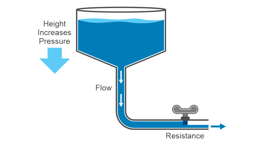
Voltage: Voltage is a force that pushes electrons through a conducting loop using a power source.
Current: Current is the measure of the steady flow of electrons that carry charge in a closed circuit.
Resistance: Resistance is a measure of how easily a material allows electricity to pass through itself.

Electric circuits and electronic components
Electric current flows inside an electric circuit, it’s a closed path made by linking different electronic components together.
The components are as follows:
- Basic electronic components: capacitors, resistors, diodes, transistors
- Power sources: signal generators and DC power supplies
Resistor: A resistor is a two terminal passive electronic component that is used to limit current in a circuit.

Capacitor: A capacitor is made of two conductive plates with an insulator between them. It stores electrical energy.

Diode: A diode is used to enable an electric current to pass in one direction only, while blocking it in the opposite direction.

Transistor: A transistor is a device that regulates current or voltage flow and acts as a switch or gate for electronic signals. Inside a computer, it detects high voltage and translates it to ON or 1.

Logic gates: A logic gate accepts inputs, transforms it into 1s and 0s and then outputs the result based on their state.
Logic gates and logic circuits
NOT gate
A NOT gate accepts an input, flips that bit, and sends it as output. A NOT gate is also known as an inverter. So, if the input is 1, the output is 0.
| Input A | Result |
|---|---|
| 0 | 1 |
| 1 | 0 |
AND gate
All other logic gates operate on multiple inputs. An AND gate accepts two inputs. If both of those inputs are "on" (represented by 1), it outputs 1. If either of those wires are "off" (represented by 0), then it outputs 0.
| Input A | Input B | Result |
|---|---|---|
| 0 | 0 | 0 |
| 0 | 1 | 0 |
| 1 | 0 | 0 |
| 1 | 1 | 1 |
OR gate
An OR gate accepts two inputs. If either of those inputs is 1, then it outputs 1.
| Input A | Input B | Result |
|---|---|---|
| 0 | 0 | 0 |
| 0 | 1 | 1 |
| 1 | 0 | 1 |
| 1 | 1 | 1 |
NOR and NAND gates
NAND and NOR gates are also known as “Universal Gates”. They can be used to build any of the other gates easily and provide the same results.
A NAND gate is an inverted AND gate. A NOR gate is an inverted OR gate.
| Input A | Input B | Result |
|---|---|---|
| 0 | 0 | 1 |
| 0 | 1 | 1 |
| 1 | 0 | 1 |
| 1 | 1 | 0 |
| Input A | Input B | Result |
|---|---|---|
| 0 | 0 | 1 |
| 0 | 1 | 0 |
| 1 | 0 | 0 |
| 1 | 1 | 0 |
In most modern computers, logic gates are built using transistors combined with other electrical components like resistors and diodes. They are all wired together to make sure that they transform the inputs in the way we expect.
Logic Circuit
A chain of logic gates together makes a logic circuit. It takes output from one gate and use it as input to another gate.
Question: What logic gate will invert a single value?
Answer: A NOT gate
Try it!
Quick crossword puzzle
Related Games